
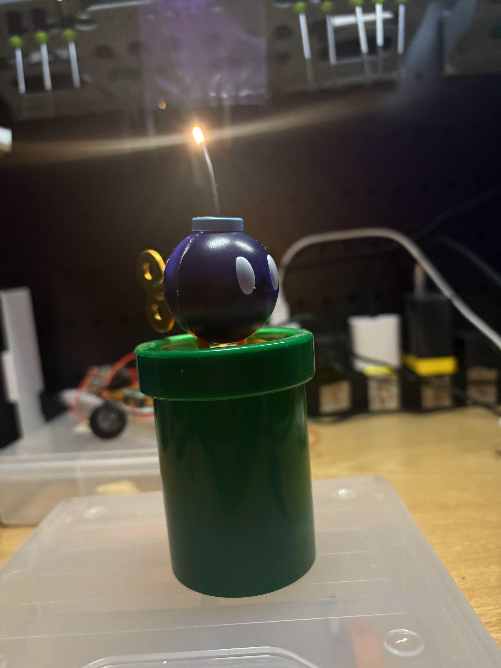
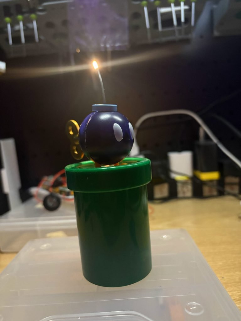
I’ve been looking to challenge myself with every build so far and I wanted to do a build that has some kind of tech function but stuffed inside a very small chassis.
What I don’t show are all the junk ( potential projects) that surrounds my work bench. Well Bob-omb has been staring at me for almost a full year and I finally have had enough.

Bill of materials
Bob-omb character figure
Flexible led filament
Resistor
Perfboard
3.7v 100mah li-po battery
Reed switch normally open

The ultrasonic hobby knife I bought made quick work of slicing through Bob-omb. This knife works great because my other option was to use a Dremel and that would have grounded away too much material. Whereas the ultrasonic knife slices right through.

The next step is to slice and grind away the inside supports to make room for the electronics.

These are the components that I planned on using with the addition of a tp4057 board so I can charge the battery.

I had to cut a small piece a perfboard just to keep everything together neatly. It’s also a good visual so I know the limited footprint that I’m working with.
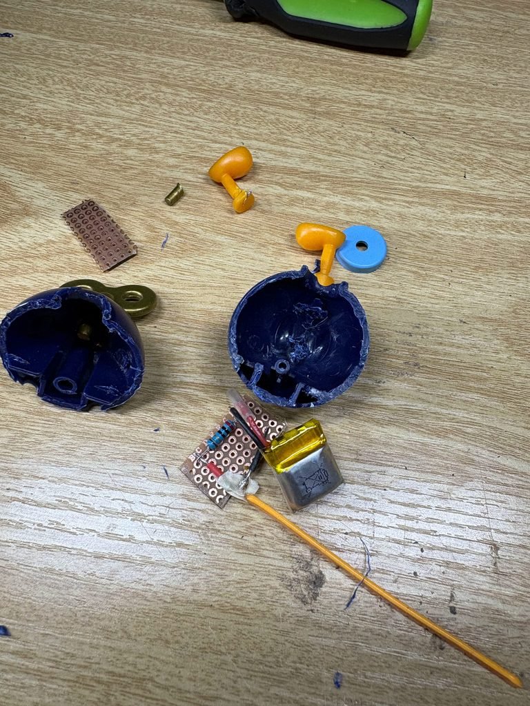
From the looks of it, it looks like everything is going to fit. The charging mod is roughly the same size as the battery.

I didn’t want to permanently solder the battery to the board. I was trying to find the smallest connectors in my pile of junk and came across this connector. I also soldered the resistor to the perfboard and the positive end of the led. Make note of the leads of the led, the positive end has a hole punched in it.

Like a damn glove! I had the battery in there too I didn’t take a picture.
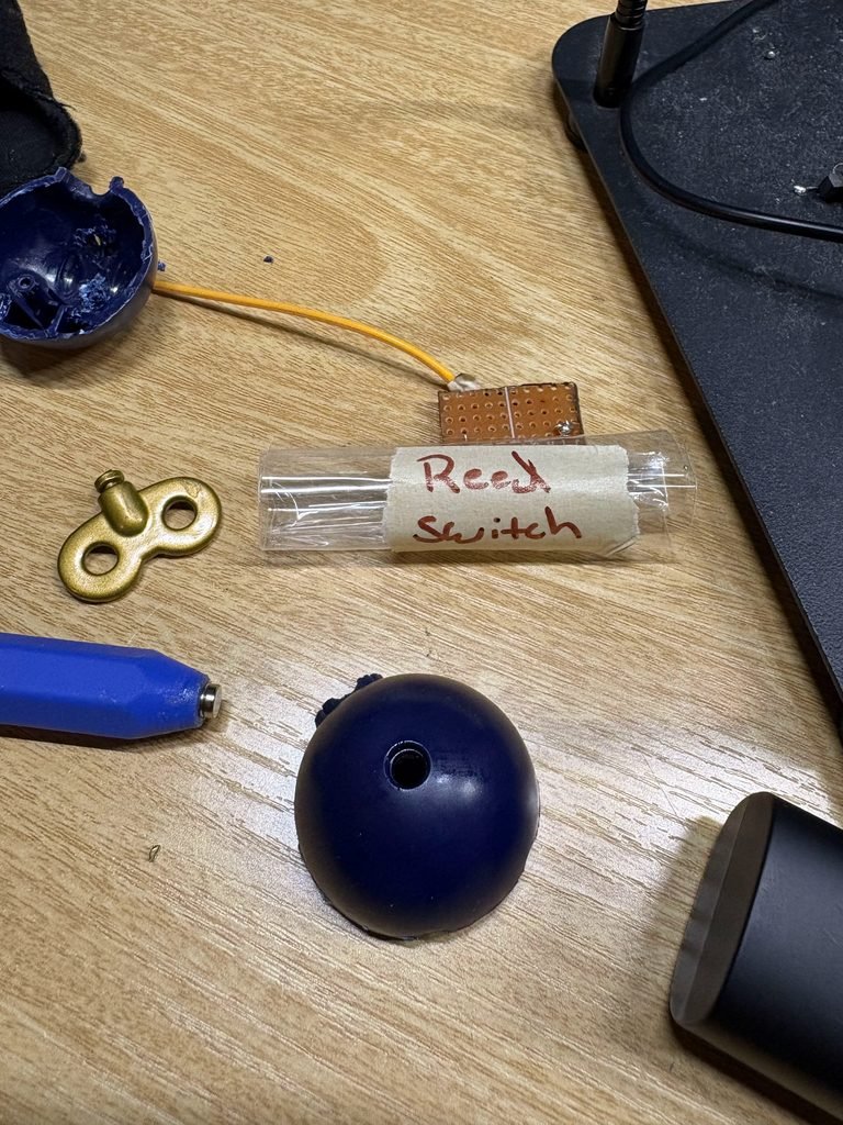
Now time for the reed switch. Reed switches are awesome to add to your project. A reed switch closes the circuit using a magnet. The one I’m using is normally open which leaves the circuit open until a magnet is introduced. A normally closed switch does the opposite. I’m using the switch here to turn the led on and off.

My plan was to have the key activate the led via magnet so placement was priority. I back filled the area behind the switch just to eliminate any rocking.
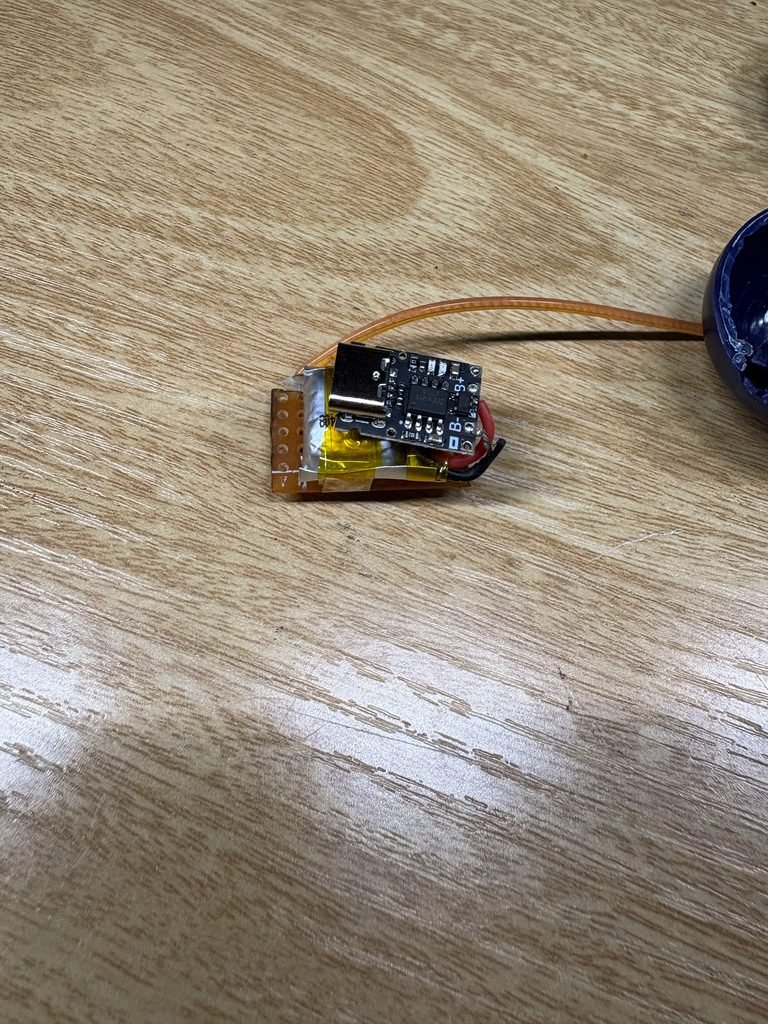
This is how the whole component looks when soldered and tape up. It actually was a very good fit and design. I did notice at this point that the pouch battery was a bit puffy so I tore down and replaced it later.

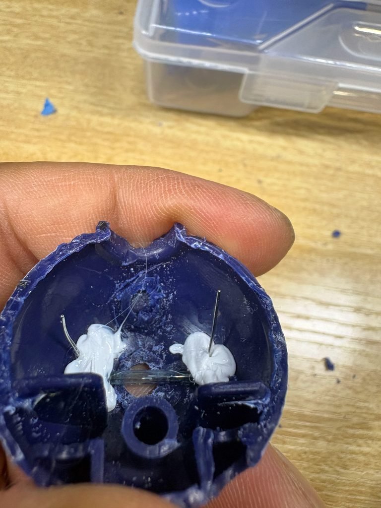
The switch was sitting a few millimeters too far from the magnets. I had to grind down the slot the key went into a bit just to gain like 4mm, I couldn’t find a strong enough magnet at the size I needed.

Finally it is time to solder and most likely force fit everything inside Bob-omb. Here I soldered the reed switch from the positive end of the battery to the resistor.
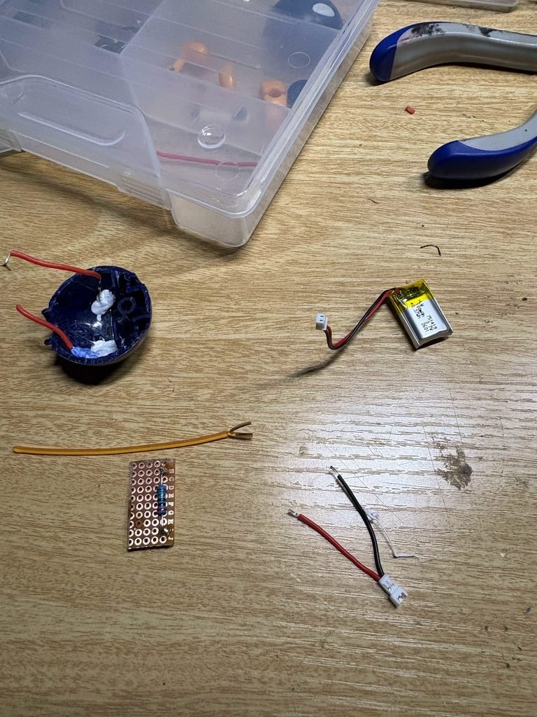
Yeah…. I had to start over. The battery had to be replaced, it was really puffy. The led stopped working for no apparent reason. Now I decided to go towards a more simpler solution. I am going to now have a removable battery instead of one that permanently lives inside.

Luckily this connector takes up as much space as the charging module would take. The only headache I could see at this point would be wire management and not having it look like a birds nest. Having helping hands like this is a huge help especially one that can be removed.
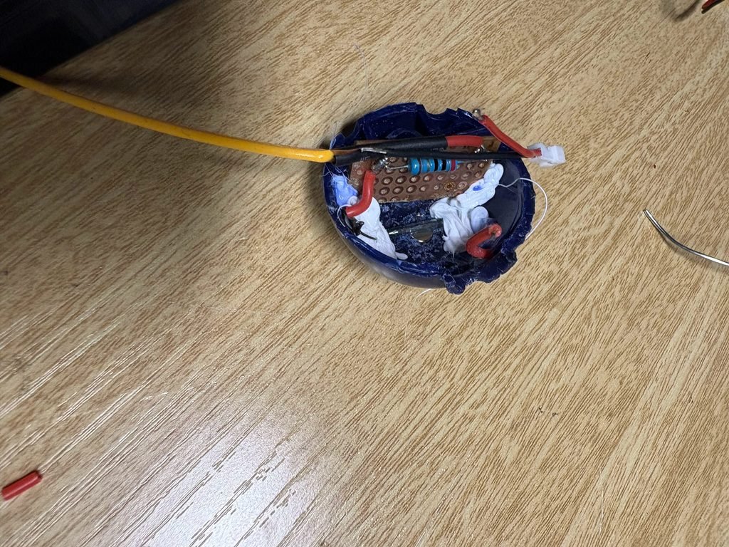
Here I soldered one end of the switch to the resistor and from the resistor to the led and from the negative lead of the led i soldered the connector’s positive. Finally, I soldered the negative lead off the connector to the reed switch.

Next step , plug in the battery and get an idea of how I want the wires to live. Needless to say there will be a lot of tucking and gluing (3D penning).
Bob-omb lights up beautifully!!! But there is a lot of light bleeding from the seam and through the plastic itself, I’ll fix this if it is noticeable but right now it’s not that bad. Next, I need to fix the wick. I only need the tip to light up and it’s also long. If I push the wick inside the body then that’ll leave less space and generate more light which will produce way more light bleeding through.
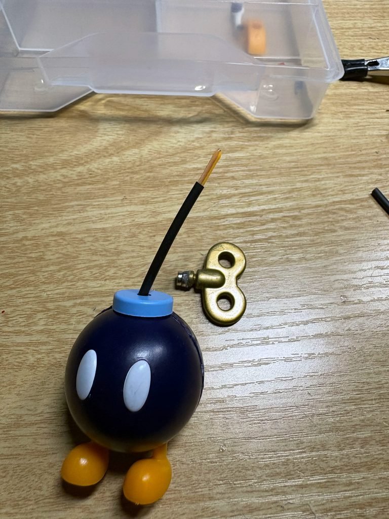
I solved the issue by keeping the wick long and using shrink tubing for the body of the wick. This eliminated a lot of the light within the body and there is zero light coming through the body of the wick. I just need to airbrush the wick-tip light hues of red, orange, and yellow. This, not only gives the illusion of the wick being lit but also helps diffuse the individual leds.
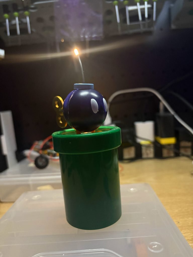

Here is the final product! This took me an afternoon to build so it was really nothing to serious, it was mostly the planning and waiting for parts that took the longest. I’m satisfied with the outcome. The seams are still visible and it’s going to stay that way so I can take the battery out and charge it. I took on the challenge of building in a limited space and I can say that I accomplished what I set out to do.
What’s would you have done different?
This post may contain affiliate links. If you buy through them, I earn a small commission at no extra cost to you, which helps fund parts and tools for future builds. Appreciate the support!